While attending the Syntax demo scene party recently, I decided to look at an effect I had not yet tried but was keen to better understand. I decided it would be FLD – Flexible Line Distance. This effect allows you to move blocks of data vertically on the screen with little processing required. Because minimal processing is needed to move huge lumps of data, it’s great for sliding bitmaps images / logos up and down the screen without having to copy any of the data each frame.

Before I began to write any code, I wanted to understand a little more about it. FLD works on character lines as it’s smallest unit. That is to say, the opportunity to generate a FLD effect can only occur between each screen character lines (8 pixels / raster lines high). We know that the first line of each new character line is a “bad” scan line, because the C64 is not only rendering the characters, but also performing a fetch on them (and subsequently eating up cycles that are otherwise available on the other 7 scan lines of the character). While these bad lines give us less cycles to play with, they also open up possibilities for some effects. This is where FLD comes in.
The FLD effect is generated by delaying the occurrence of the next bad scan line. When the C64 finishes rendering the 8th line of the current character data, it’s ready for a bad scan line to fetch the next character row data. If we delay that bad scan line, the C64 has nothing to draw and instead of rendering the next screen character line, it will instead render the last byte of the current video memory ($3fff for example). This byte will be repeated across the screen, for each raster line until the next bad line occurs.
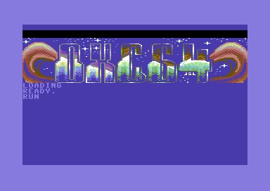
In the screen shot above, I’ve set $3fff to $ff so it’s a solid line. I found this useful during debugging to ensure the effect was working correctly.
Because of this behavior, we can move character data down the screen by as many pixels (scan lines) as needed. Being more creative, we can adjust how many scan lines to delay the next bad line for to add some movement. The last thing I wanted to understand is how does the C64 know which scan line to generate the next bad line on. This is actually controlled by the lowest 3 bits of the screen control register located at $D011. These 3 bits also control the hardware vertical scroll and can be a value of 0 to 7.
By default, this register contains the value $1b, with the state of the lowest 3 bits being 011 (value of 3). By modifying these 3 bits just before the next bad scan line occurs, we can continually delay the rendering of the next character line for as long as we want. With that in mind, I decided to put some code together.
I will be triggering interrupts at certain points down the screen to perform different tasks and they should look something like this.
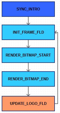
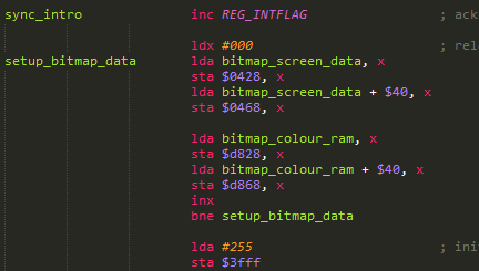
The sync_intro interrupt is used to perform some set up for the example. Here, I use it to relocate the bitmap screen and colour ram data to the desired locations. I also set $3fff to $ff (255) as I found it useful for debugging. Normally this bitmap should have a black background – i’ve left it blue so I can see the FLD scan lines.
The bitmap data is located at the end of the file, which consists of data for screen RAM, colour RAM and the bitmap itself.
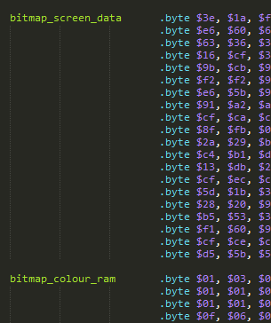
The bitmap data itself is uncompressed and will live at $2140, which places it on the second screen line. I’ve included alignment commands in the source code to pad the compiled .prg file to ensure the bitmap data is automatically loaded at the correct location without having to write additional code to relocate it.
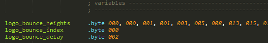
At the end of the code are 3 variables which are used for this FLD effect. The first is simply a delay, which is used to adjust the frequency the FLD height index changes. The second is an index into the FLD height table. This will start at 0 and go to 15, before looping back to 0 again. The last variable is a small 16 byte table containing heights – how many FLD lines to render. It’s a hand made bounce effect – rough, but perfect to test the routine.
Once the sync_intro interrupt is completed, it then adjusts the interrupt to occur at scan line 15 and call init_frame_fld. This is a very small routine and simply resets the screen control register at $D011 to its default value of $1b. This will reset any changes we make to the lower 3 bits during the FLD effect for the previous frame. Because I’m not modifying any of the other bits on $D011, I’m safe to just assign $1b.
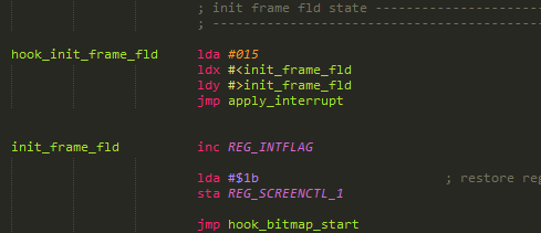
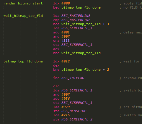
Once the init_frame_fld interrupt is complete, it sets up render_bitmap_start in the interrupt chain, which will occur on line 57 – just before the next bad scan line occurs. Here is where the FLD magic occurs. We now want to adjust the 3 lower bits on $D011, pushing the next bad scan line back 1 for each FLD line we want to render. This routine does not need to be cycle exact to work.
Once the desired number of FLD lines have been rendered, we wait for the raster to be in position for the bitmap and then set up the bitmap for rendering. This code could be more efficient and the time spent waiting during the FLD put to more use – but for the example, this should be nice and clear.
Once this interrupt completes, it then chains to a render_bitmap_end interrupt which switches bitmap mode off. The final link in the interrupt chain is a small update routine to adjust the FLD height each frame.
With the code together, running this gives us the FLD effect in action. The height of the FLD changes based on stepping through a simple height look up table to generate a rough bounce effect.
Great! We now have an FLD in action, moving an 8 character high logo vertically. Let’s extend this example a bit further. From above, I now have an FLD effect performing a simple bounce effect on the logo. The impact this has on the rest of the screen can be seen with the remaining lines (loading, ready, run) being pushed down as the FLD height changes. If we want to use the rest of the screen to perform some character based effects which we don’t want to have constantly moving due to the FLD, then we need to counter this movement. A solution here would be to create a second FLD effect that occurs after the logo. That way, we can keep the rest of the screen at a constant position.
To do this, the same FLD code can be used in the render_bitmap_end interrupt handler. The update routine is extended with a few extra lines to calculate how many fld lines to balance the logo bounce with. This gives us a padded section below the logo, which decreases as the FLD effect above the logo increases.
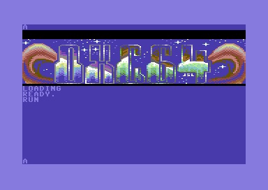
With the FLD effect height at 0 (notice the position of the screen text):
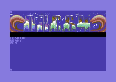
The FLD height has increased and the padding below has decraesed. The screen text below the logo remains in the same position. I placed the “A” character in two places during testing to help ensure the character positions were all correct.
We now have a bouncing logo, using FLD and a stable bottom section of screen to perform other character based effects in. So that’s a small introduction to generating a simple FLD effect. There is a lot more you can do with it from here and opportunity to join it with other effects to create some neat demo effects.
The full source code for the example can be found here: Github
A compiled .prg of the sample can be downloaded here: fld.prg
Can’t stop myself from saying “boing-boing-boing-boing” while watching that logo bounce. I feel like the code portion is beyond my understanding but it is still fascinating to see you go through this process. Glad to see you are still moving forward!
Thank you for this tutorial! I haven’t written 6510 machine code since around 1990, but it was gratifying to be able to understand your examples and finally know what makes FLD work.